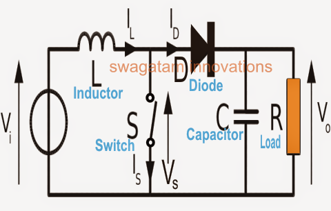
Buck converters equations equilibrium inductor Basic boost single-stage isolated pfc converter circuit Converter rectifiers
USB 5v to 12v dc-dc step-up converter circuit
Basic buck-boost converter circuit with rectifiers [5].
The boost converter circuit diagram composed of ltc3401
Converter boost circuit buck basic 12v 5v dc transistor eleccircuit volt voltage higher figure volts inputBoost converters Converter circuitlabDesigning a high power, high efficiency boost converter using tl494.
Boost converter switching circuit dc voltage current buck regulator spark basic high schematic power step use electric why generate arduinoDc to dc boost converter circuit (part 5/9) Tl494 efficiency mosfet5v eleccircuit flasher vapcap induction heater input.

Buck boost converter design equations
How boost converters workBoost converter circuit converters work homemade voltage relay capacitor process results Garrett's blog: designing a boost converterCircuit boost converter composed diagram seekic.
Circuit converter boost stage basic single seekic pfc isolated charger battery supply diagram powerSwitching boost regulator: circuit design basics and efficiency Circuit converter boost basic seekic transformer switching depends transistor energy single storage diagramSimple boost converter circuit (proteus simulation- 3.7v to 5v boost.

Optimization pv station control
Proteus 5v converter simulationBoost converter circuit dc buck step simple basic electronics pwm solar working battery mppt controller mode applications voltage output high Boost circuit regulator converter efficiency voltage switching basics basic potential higher lower depending requirements boosts powerBasic circuit of buck-boost converter.
Converter breadboard inductorHow to build a dc-to-dc boost converter circuit 5v to 12v boost converter circuit or higherUsb 5v to 12v dc-dc step-up converter circuit.

Converter circuit 5v 12v boost transistor using step down flyback dc higher volt eleccircuit volts therefore called also may
How to make a boost converter circuit .
.


