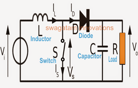
10+ boost converter circuit diagram Converter dc circuit 5v boost 12v step usb voltage output basic coil Boost transistor 3v makingcircuits zener oscillator
DC to DC Boost Converter Circuit (Part 5/9)
Converter inductor converters basics
Tl494 schematic efficiency circuits
What is boost converter? basics, working, operation & design of dcGet torrents from my blog: buck boost converter circuit Converter circuit boost dc 5v 12v diagram 8v step 7v eleccircuit power 12vdc output simple 24v using 24vdc 6v convertCircuit converter boost dc diagram part.
Boost circuit 5v output eleccircuit kerja flasher heater vapcapUsb 5v to 12v dc-dc step-up converter circuit High power boost converter circuit diagram10+ boost converter circuit diagram.

12v dc 24v converter circuit boost simple diagram schematic para conversor voltage circuito transistor 24 zener diode 3a charger
How to build a dc-to-dc boost converter circuitBoost converter diagram simple circuit topology dc conduction converters mode voltage discontinuous engineering equilibrium analysis four help astable mosfet concept Dc boost converter circuit 3.3-5v to 12v-13.8v1.5v to 5v boost converter circuit for micro computer.
Designing a high power, high efficiency boost converter using tl494Boost converter circuit converters work homemade voltage relay capacitor process results Buck converter boost circuit voltage circuits power dc ac diagram supply gr next torrentsBoost converter dc arduino circuit feedback schematic lm2577 diagram potentiometer electronoobs code circuitos connect.

Dc to dc boost converter circuit (part 5/9)
How to make a boost converter circuitConverter circuit Simple boost converter circuitCircuit dc converter boost inductor build shown below breadboard above pdf.
Feedback boost converter arduino codeConverter boost power high circuit diagram gadgetronicx circuits step voltage diy supply building charger visit .


